There's a reason they're called "movies." They're supposed to move. Your eyes are keyed to follow motion, and the constant revelation of new information in a moving shot holds your interest longer. Thus, while four seconds might be about the maximum comfortable length for a static shot, shots in which the camera or subject are moving extensively can often last more than a minute without feeling slow at all. Storyboards made entirely from static images make it hard to judge active shots. It's useful, therefore, to be able to insert some movement at the storyboard phase by panning and zooming a drawing. Here I'm going to demonstrate such an animated storyboard using Inkscape and Blender.
Making Movies with Free Software
This article is part of an on-going series on the challenges I've faced in producing two free-licensed movies, Marya Morevna, through the Morevna Project and Lunatics, which we are working on as Anansi Spaceworks.
For the cinematography in "No Children in Space", I'll be using a lot of moving camera work in counterpoint to montage sequences. This is one of those things that 3D animation is particularly good at, and I intend to make good use of it. The beginning of the film, will, however, be using a lot of locked-off "cel animation" styled shots (that is, while they might not actually be implemented with cels, I intend to use a lot of flat composition that resembles it). These, of course, work particularly well with a pan-and-zoom approach in the animatic phase. The example I've picked out here is actually meant to be the second shot in the film, shot "0020-010" in the system I've adopted for numbering shots.
Getting the Tools
The tools I use in this example are common packages in free software distributions. Specifically, I'm using the vector-graphics editor Inkscape, version 0.47 (but earlier versions would do the same job) and Blender, version 2.49b. These are the stock versions in Debian GNU/Linux's "Squeeze" distribution (the current "testing"), and are likely to be found in many other distributions as well. Use your standard package tools to install.
I'll probably upgrade to Blender 2.5x when we begin actual production, but 2.4x provides all we need for producing an animatic, is better documented, and has a very stable Debian package at this time.
Laying out the shot in Inkscape
After searching far and wide for an image or drawing of the correct train car for this shot, I finally found one in a familiar place -- Wikimedia Commons. The car is known as a "Platz-Cart" or "Плацкартный вагон" in Russian, and is a kind of sleeping car that would realistically be used on the railway in the film (I'm not much of a trainspotter myself, but I like to be as accurate as possible). The drawing is attributed to "Glucke" (Wikipedia username), and is licensed CC By-SA 3.0.
I start laying out the shot by loading this drawing into Inkscape, scaling it up to a more comfortable size (approximately "US Letter" size -- this is not technically necessary, but it makes Inkscape defaults make more sense). I ungroup; delete unnecessary material; regroup; and then cut and paste the drawing to a background layer in my drawing.
After searching far and wide for an image or drawing of the correct train car for this shot, I finally found one in a familiar place -- Wikimedia Commons
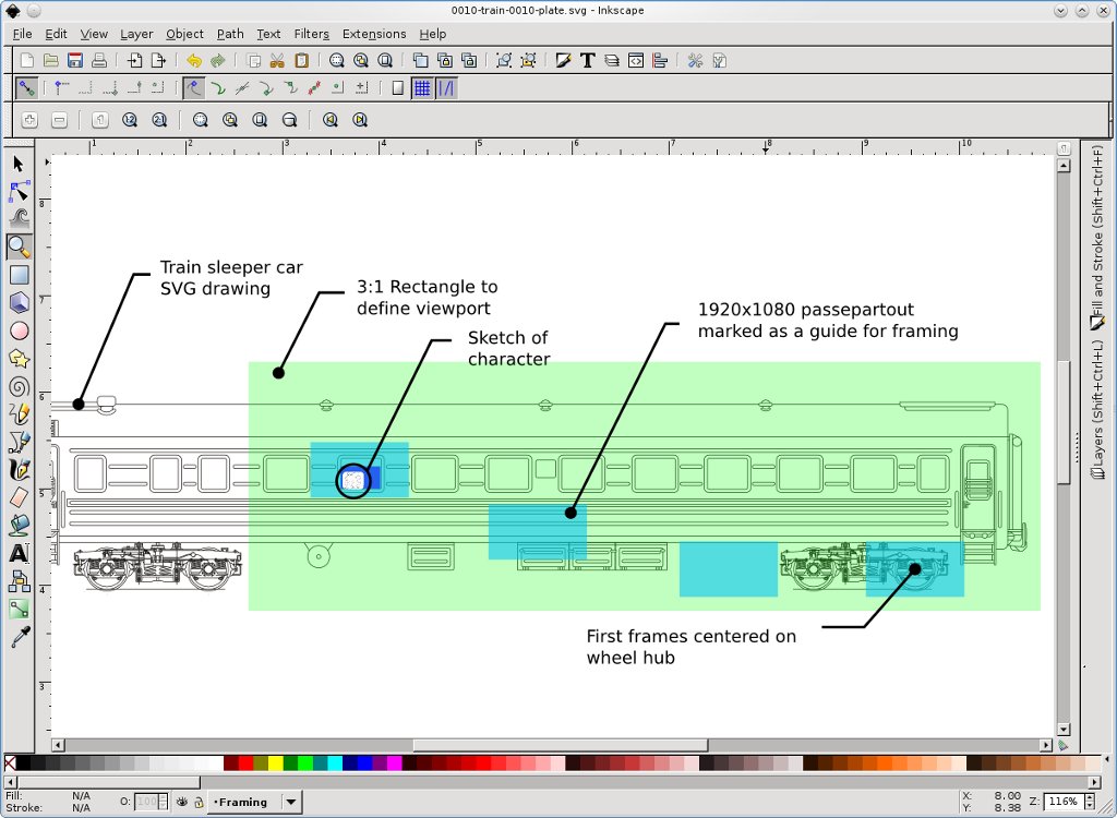
On top of this, I build up additional layers. The drawing of the character is from my original storyboard sketch. I frame the character and insert her into the appropriate train window.
Next, I drop some framing rectangles to indicate where I want the camera to be, and how tightly I want it to be zoomed in. I'm designing for 1920x1080 widescreen HD video, so I create 16:9 aspect-ratio rectangles to represent the "passepartout" -- the viewport which will be seen on screen.
The beginning of the shot is meant to carefully line up the circle of the train wheel with the geometry of the previous shot of the full Earth. I actually do this by importing the previous shot and matching a circle and the passepartout rectangle to that composition -- then I line up the scale and position with the train wheel in the train drawing.
I copy the passepartout rectangle a few times and move these to positions along the track I want to follow during the shot. These will serve as a check of the framing as the shot is animated in Blender.
I decided (after testing an earlier version of this shot) to push in at the end of the shot, centering on the character. So, I also make a scaled-down passepartout to indicate the end target for the shot.
I copy the passepartout rectangle a few times and move these to positions along the track I want to follow during the shot
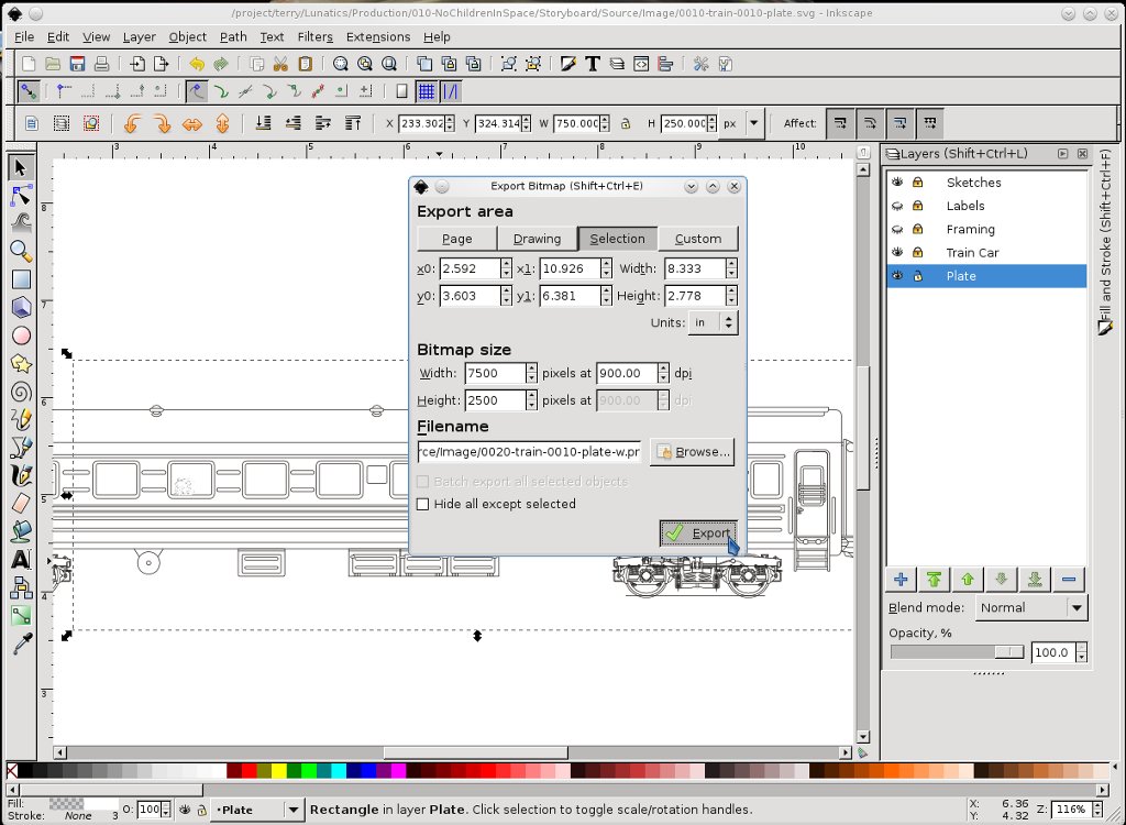
Finally, I create a rectangle to define the "background plate" that I will use in Blender. This needs to be large enough to include all of the shot (i.e. include all of the passepartout rectangles that I have created thus far). It also needs to have a simple, easy-to-remember aspect ratio to make it simpler to import it into Blender correctly. I choose 3:1 and edit the width and height of the rectangle accordingly. I export the selection at 7500x2500 pixels (900dpi).
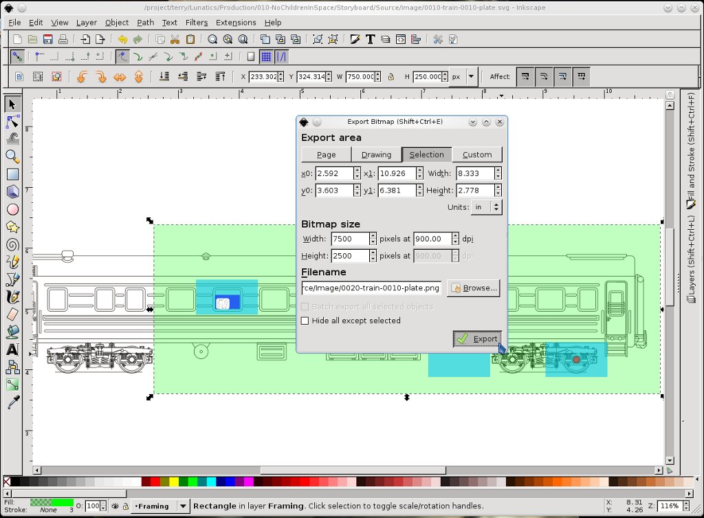
The final layout is visible in Figure 1. I export this to a PNG image by selecting the background plate rectangle and exporting the selection from Inkscape (the label layer was created just for this column -- I turned that off before exporting, of course). I use a high resolution, because we're going to be zooming in pretty close to get the desired shot and I don't want the final images to pixellate too much.
Importing the background plate into Blender
The basic idea is to map the image onto a "plane" (mesh object) in Blender and position a camera in the right spot to photograph the desired viewport on this "background plate." Then I'll animate the camera to move across the plate to get the panning and zooming motion that I want.
The basic idea is to map the image onto a "plane" in Blender and position a camera in the right spot to photograph the desired viewport on this "background plate"
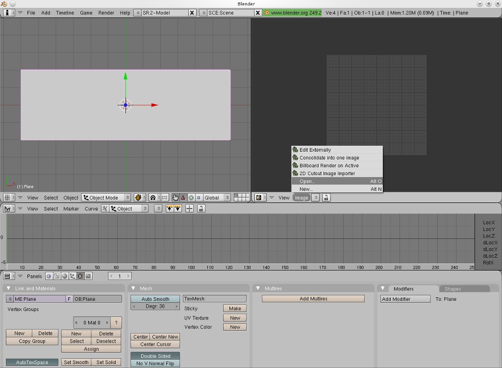
I start by opening Blender. There are some default objects in the scene, but I want to start with an empty field, so I use the "A" key to select all objects and "delete" to delete them. The cursor is already at the center of the Blender world, otherwise I'd move it there. Then I type the spacebar to get the "Add" menu and add a "Mesh" "Plane" -- this will be a mesh consisting of a square of four points (vertices).
I need a 3:1 ratio, and I'd like it to be slightly larger. So, I key 'S', 'x', '6', 'enter' to scale by exactly 6 horizontally, and 'S', 'y', '2', 'enter' to scale by exactly 2 vertically. The result is a 12x4 Blender unit (BU) plane object. This will hold the "background plate" image.
At this point, I right-click on the window boundary to split areas and create a UV image editor window on the right side of the 3D window. I also create another window along the bottom for the Ipo curve editor (clicking right on the boundary between the two windows on the far left to get the "Split areas" menu). This arrangement is shown in Figure 3.
Making sure the plane is selected, I click on the "Materials" tab (or key 'F5'). In this panel, I need to create a new material, which I just call "BkgPlate", and set it to be "Shadeless" and use "TexFace" (which means the image texture will be used for coloring it).
Returning to the UV editor window, I use "Image"→"Open" to load the background plate image that I exported from Inkscape.
With the plane still selected, I key 'tab' to go into edit mode, and then key 'U' and choose "unwrap." The four vertices from the plane now appear mapped into the UV editor, as a square. Setting the "Draw type" selector on the 3D window, I can now see the resulting mapping in the 3D window.
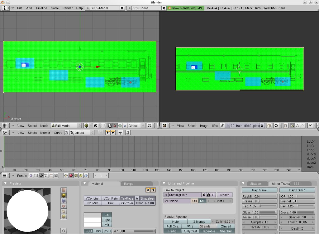
For whatever reason, the default unwrap results not only in a square arrangement, but also one which is "upside" down as viewed in the 3D window. I fix this using scaling and rotation operations on the vertices in the UV window. I wind up with the points aligned to the corners of the image in the UV editor, and the image appears rightside up in the 3D window. It's also not stretched or squashed oddly, and the whole plane is filled with the image. Figure 4 shows the situation at this point.
Adding the camera
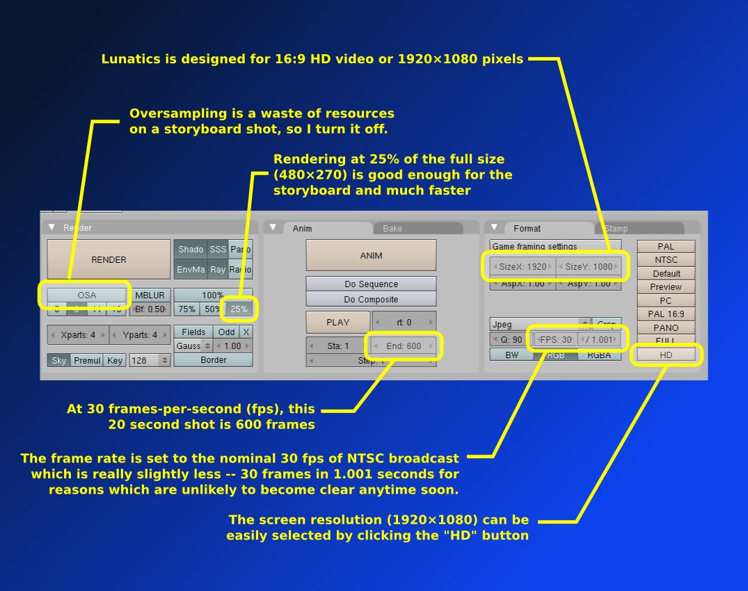
Since I'm about to start setting up cameras and animation, I need to fix the animation settings. These are shown in Figure 5: Lunatics is being designed for "HD" 1920x1080 resolution, at 30 frames-per-second (fps), and the 1.001 second timebase as used for NTSC video. I also set the shot length to 20 seconds (600 frames at 30 fps). When I'm done, I make sure to reset the frame counter back to 1 for the beginning of the shot.
Now, I position the cursor exactly centered on the wheel, using the XY view (which you can get by keying the '7' on the number pad), by left-clicking. I then switch to the side view with 'numpad 3', and position the cursor vertically (along the Z axis), just placing it a couple of blender units above the plane. Now I key spacebar, "Add", "Camera" to add the camera. Fortunately, it will already be oriented correctly -- looking down along the Z axis at the plane, with the top of the field facing the positive Y direction.
Since I'm about to start setting up cameras and animation, I need to fix the animation settings
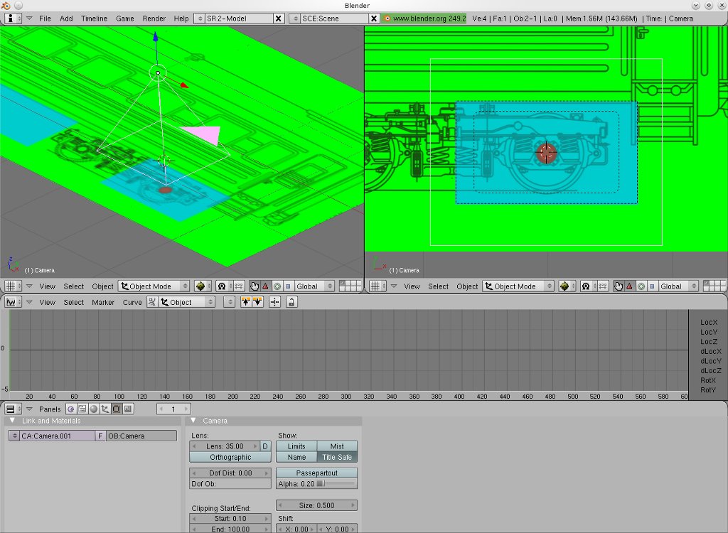
At this point, I replace the UV editor window with another 3D view, and I select 'numpad 0' to get the camera-eye view. This shows the plane, and with the image mapping on, I can see how my shot compares with the field I drew onto the background plate. By manipulating the camera with the axis-movement handles (see Figure 6), I can track the camera left, right, up, or down, as well as towards and away from the plane. With such movements, I align the actual passepartout with the passepartout rectangle I drew on the background plate earlier in Inkscape.
Why not use an orthographic camera?
You may notice that I am using a normal "perspective" camera for this shot (at the default "35mm" focal length). It might seem more appropriate to use "orthographic."
In fact, I tried both, but there seems to be a problem setting Ipo points for the Orthographic camera's "Scale" parameter (there isn't one, there's just "Lens", and using that results in a weird clipping behavior -- the scale won't go below "1.000"). If there were multiple planes in this shot, it might be a problem, but with a single plane, there are no perspective effects to worry about.
With the perspective camera, I can "push in" (change the Z coordinate) instead of "zooming" (changing the field of view), and the effect will be the same (if this were a 3D scene, they would look very different). In any case, animating the camera along the X, Y, and Z axes is much easier than trying to animate the camera parameters so this is much more convenient.
Animating the camera
Now the camera is aligned with the first position. With the camera selected, I set the frame counter to "1", and I key 'I' to set an interpolation ("Ipo") key frame. I select "LocRot", which means to save both the location and rotation state of the camera. This marks the camera's position at frame one.
Now, in the Ipo editor window, I move the line to 60s (actually I move it to fifty-something, and then nudge it to exactly 60 with the arrows on the frame-entry widget). Of course, this is two seconds into the shot -- which is about how long I want the shot to linger on the wheel before it begins to move. So, I repeat the same procedure to create a second key here.
Next, I set the frame counter to three seconds later in the shot (five seconds total), moving to frame 150. Then I reposition the camera, using the arrow handles in the oblique 3D view on the left, while watching the camera-eye view on the right. I line it up with the second passepartout rectangle on the drawing. And of course, I repeat this same procedure until I reach the frame over the train window at about frame 300.
The last ten seconds of the shot are meant to be a slow zoom
The last ten seconds of the shot are meant to be a slow zoom. So now, I jump to frame 600 (the end of the 20 second shot), and then I move the camera down towards the plane by using the Z-axis arrow in the oblique view. This makes the plate look larger in the camera-eye view, and I combine this motion with the X and Y axis motions to frame the final close-up target. I set another Ipo key frame here, and that defines the camera motion, which follows this plan:
| Seconds | Frame | Target |
|---|---|---|
| 0-2 | 60 | Hover on wheel |
| 2-5 | 150 | Track to 2nd target |
| 5-7 | 210 | Track to 3rd target |
| 7-9 | 270 | Track to window |
| 9-10 | 300 | Hover on window |
| 11-20 | 600 | Zoom in to character |
Targets along moving camera track
It's possible to do additional manipulation of the Ipo curves. It occurred to me, for example, that it might be good to introduce a visible "bump" when the train wheel starts to turn, or to introduce a gentle vibration during the pan, to emphasize that the train is moving. But that level of detail is probably overkill for an animatic, so I'll leave it for later.
Results
The final results from the above steps are shown in the video below.
Figure 7: Video with framing marks included
To create the final, usable shot, I go back to Inkscape and export a new background plate image (Figure 8), but this time without any of the framing marks. I then load this using the UV editor.
The final result is in Figure 9 -- a video with the desired moving camera work, ready to be incorporated into the animatic with other shots.
Figure 9: Final, ready-to-use shot for storyboard animatic
Licensing Notice
This work may be distributed under the terms of the Creative Commons Attribution-ShareAlike License, version 3.0, with attribution to "Terry Hancock, first published in Free Software Magazine". Illustrations and modifications to illustrations are under the same license and attribution, except as noted in their captions (all images in this article are CC By-SA 3.0 compatible).